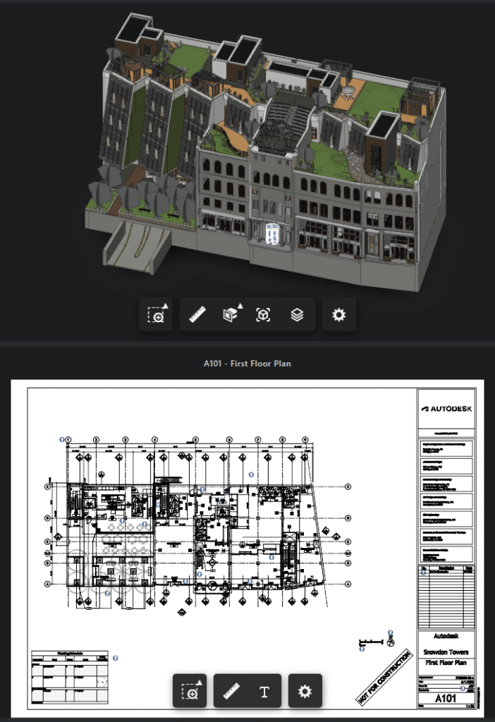
A commonly requested feature when working with digital twins, is to show 3D data (like building models) and 2D data (like floor plans) alongside another. With the Autodesk Platform Services (formerly Forge) it is easy enough to display two separate viewers on the same page.

Showing the sheet with the ground floor plan is easy enough – but where is this door?
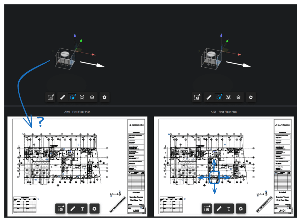
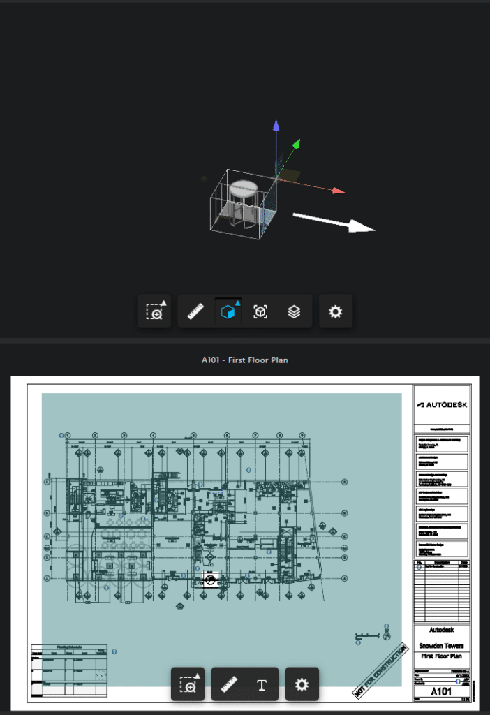
Oftentimes a followup request is about interactivity between those two viewers. In particular, when using the Section Analysis feature in 3D, users could feel quite lost in 2D, so our idea was to highlight the section box in 2D as well.

Oh no – isolating the door via a section box leaves me with no reference points for orienteering on the sheet. Wouldn’t it be nice to see where I am on the sheet like in the sketch on the right?
Preparation
In the following, we assume the reader to be familiar with the Autodesk Viewer SDK. We use TypeScript which is sadly not fully supported for what we want to do here, so please bear this in mind whenever you encounter TypeScript warnings while executing some of the following code.
An Autodesk blog post from 2020 serves as a useful basis for our approach, by showing how to map single points between 3D space and 2D sheets.
For simplicity most of our code is contained within a single function – which is an event handler registered for the Autodesk.Viewing.CUTPLANES_CHANGE_EVENT event of the 3D viewer (const handleCutPlanesChangedEvent = async (e: {planes: THREE.Vector4[]}) => {...}).
The relevant portions outside our handler, which are left as an exercise for the reader:
v3Dandv2Dare both instances ofAutodesk.Viewing.GuiViewer3Dand show 3D and 2D representations from the same Revit (.rvt) file hosted on the Autodesk Construction Cloud (ACC).- You have loaded AEC data for the model and stored it in a
aecvariable. v2Dshows a Revit sheet with at least one viewport.v2Dhas an overlay scene with a constant, known identifier (v2D.overlays.addScene(SHEET_OVERLAY)).
Implementation
First we obtain an arbitrary viewport on the sheet – this can be extrapolated for any number of viewports if so desired.
const model2d = v2D.model
const sheetGuid = model2D.getDocumentNode().guid()
const vp = aec.viewports?.filter((v) => v.sheetGuid === sheetGuid)
For this viewport, we now obtain the matrix for the transformation from 3D space to 2D space.
const inverseModelToViewerTransform = v3D.model.getInverseModelToViewerTransform()
const sheetUnitScale = model2d.getUnitScale()
const sheetMatrix: THREE.Matrix4 =
  // @ts-ignore Sadly Autodesk.AEC.AecModelData is not typed.
  Autodesk.AEC.AecModelData.get3DTo2DMatrix(vp, sheetUnitScale)
    .clone()
    .multiply(inverseModelToViewerTransform)
sheetMatrix is a 4×4 Matrix that can be used to transform a point, but we also need transformation of directional vectors (like a normal vector), so we generate a 3×3 Matrix sheetMatrix3, simply by dropping the last row and column of sheetMatrix.
We only want to draw onto the given viewport, and not the entire sheet, so we obtain the 4 lines delimiting the rectangular viewport.
const bounds: { min: THREE.Vector2; max: THREE.Vector2 } =
  //@ts-ignore
  Autodesk.AEC.AecModelData.getViewportBounds(vp, sheetUnitScale)
const delimiters = [
  new THREE.Line3(
    new THREE.Vector3(bounds.min.x, bounds.min.y, 0),
    new THREE.Vector3(bounds.max.x, bounds.min.y, 0)
  ),
  new THREE.Line3(
    new THREE.Vector3(bounds.max.x, bounds.min.y, 0),
    new THREE.Vector3(bounds.max.x, bounds.max.y, 0)
  ),
  new THREE.Line3(
    new THREE.Vector3(bounds.max.x, bounds.max.y, 0),
    new THREE.Vector3(bounds.min.x, bounds.max.y, 0)
  ),
  new THREE.Line3(
    new THREE.Vector3(bounds.min.x, bounds.max.y, 0),
    new THREE.Vector3(bounds.min.x, bounds.min.y, 0)
  ),
]
The planes argument passed to the handler contains all cutplanes, each represented in Hesse normal form by a 4 dimensional vector (the first 3 elements being the normal vector, the 4th being the scalar distance). We split these components and map the planes from 3D to 2D space, while also dropping all planes that are parallel to the sheet, since they are not interesting for us.
const cameraForward = new THREE.Vector3(
  vp.cameraOrientation[0],
  vp.cameraOrientation[1],
  vp.cameraOrientation[2]
)
const planesOnSheet = planes
  .map((p) => {
    const normal = toV3(p) // toV3 is a helper function dropping the fourth element of a Vector4
    const origin = normal.clone().multiplyScalar(-p.w)
    normal.applyMatrix3(sheetMatrix3).normalize()
    origin.applyMatrix4(sheetMatrix)
    const constant = normal.dot(origin)
    return { origin, normal, plane: new THREE.Plane(normal, -constant) }
  })
  .filter(({ normal }) => Math.abs(normal.dot(cameraForward)) < 0.001)
Each plane corresponds to one of the delimiters in the sense that it replaces this delimiter with itself. To find the corresponding delimiter, we consider only the lines parallel to the plane, and then find the one that the normal vector points towards.
We separately check whether any cutplane is moved out of the viewport in the direction of its normal vector, in which case we consider the entire viewport hidden and draw a rectangle to hide it completely. To identify this situation, we check whether both parallel delimiters are behind the plane.
const material = new THREE.MeshBasicMaterial({
  color: 0x224444,
  side: THREE.DoubleSide,
  opacity: 0.5,
})
const sheetNormal = new THREE.Vector3(0, 0, 1)
if (
  planesOnSheet.some(({ plane, origin, normal }) => {
    const p1 = origin.clone().add(normal)
    const p2 = origin.clone().sub(normal)
    const parallelEdges = delimiters.filter((line) => !plane.intersectLine(line))
    return parallelEdges.every(
      (l) => p1.distanceToSquared(l.start) < p2.distanceToSquared(l.start)
    )
  })
) {
  const geometry = new THREE.Geometry()
  geometry.vertices.push(
    delimiters[0].start,
    delimiters[1].start,
    delimiters[2].start,
    delimiters[3].start
  )
  geometry.faces.push(new THREE.Face3(0, 1, 2, sheetNormal))
  geometry.faces.push(new THREE.Face3(0, 2, 3, sheetNormal))
  const mesh = new THREE.Mesh(geometry, material)
  v2D.impl.addOverlay(SHEET_OVERLAY, mesh)
  v2D.impl.invalidate(true, true, true)
  return
}
On the other hand, if the plane lies between the two delimiters, we want to draw the rectangle between the line and the corresponding delimiter.
planesOnSheet.forEach(({ normal, origin, plane }) => {
  const geometry = new THREE.Geometry()
  // Find 4 corners to draw a rectangle.
  // First find 2 points where the plane intersects the bounds.
  delimiters
    .map((line) => plane.intersectLine(line))
    .filter((x) => x)
    .forEach((p) => geometry.vertices.push(p))
  // Only if those 2 points were found, find the 2 points of the bounding
  // line parallel to the plane, in the correct direction.
  if (geometry.vertices.length) {
    const p1 = origin.clone().add(normal)
    const p2 = origin.clone().sub(normal)
    const correspondingEdge = minBy(
      delimiters.filter((line) => !plane.intersectLine(line)),
      (l) => p1.distanceToSquared(l.start) - p2.distanceToSquared(l.start)
    )!
    // This check ensures we add the vertices in the correct order to obtain the desired triangles at the end.
    const p0 = geometry.vertices.findLast((_) => true)!
    if (
      p0.distanceToSquared(correspondingEdge.start) <
      p0.distanceToSquared(correspondingEdge.end)
    ) {
      geometry.vertices.push(correspondingEdge.start, correspondingEdge.end)
    } else {
      geometry.vertices.push(correspondingEdge.end, correspondingEdge.start)
    }

    geometry.faces.push(new THREE.Face3(0, 1, 2, sheetNormal))
    geometry.faces.push(new THREE.Face3(0, 2, 3, sheetNormal))

    const mesh = new THREE.Mesh(geometry, material)
    v2D.impl.addOverlay(SHEET_OVERLAY, mesh)
  }
})
Finally we force a re-render of the 2D viewer in order to show our changes.
v2D.impl.invalidate(true, true, true)

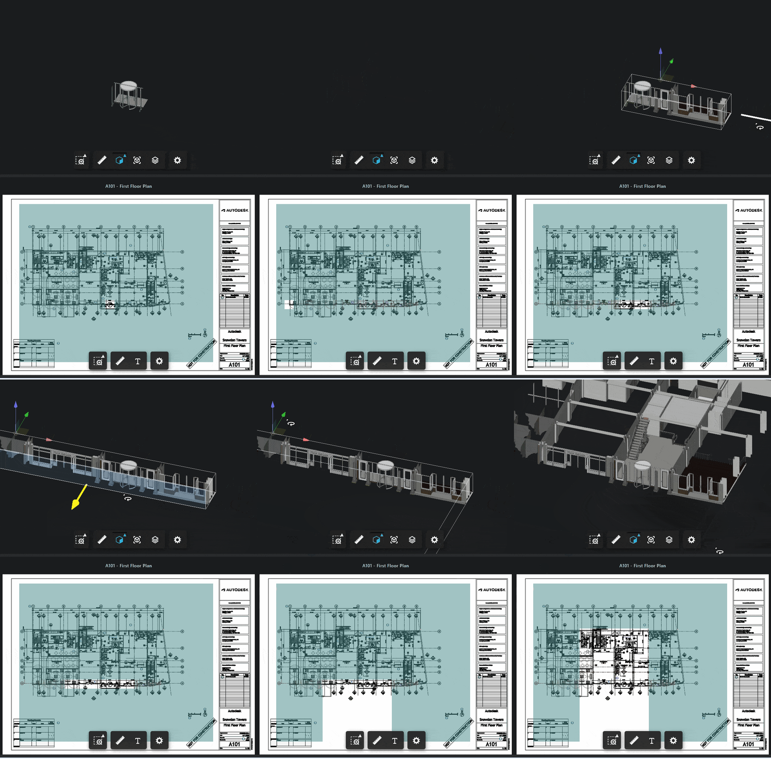
There we go, by masking the hidden areas we can easily identify our door on the sheet.
Conclusion
We have shown how to use data provided by the APS Viewer together with linear algebra and THREE.js in order to highlight cutplanes on sheets, to allow the user to navigate through the model more easily.
